Power Distribution Networks (PDNs) must provide many low-noise DC power rails for sensitive loads such as microprocessors, DSPs, FPGAs and ASICs. The quest for more speed and higher density means faster edge rates, higher frequencies and more rails, with lower voltage levels and higher currents. This places pressure on design for both signal integrity and power integrity. The goal of making power integrity measurements is to validate that the voltage and current reaching the Point of Load (POL) meet the load’s power rail specifications under all expected operating conditions. Special attention is required to accurately measure millivolts of power rail noise at GHz frequencies.
Noise specifications on power rails can go up into MHz or GHz frequency ranges with amplitudes in millivolts. This makes probing a challenge.
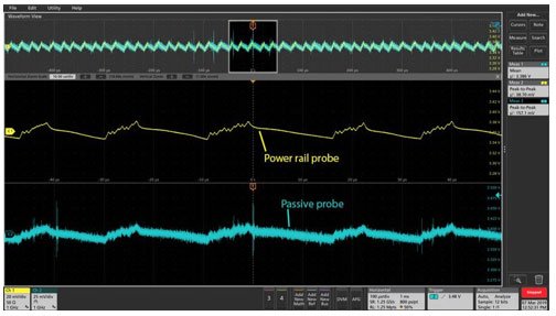
The high-impedance 10X passive probes that come with oscilloscopes may have enough bandwidth, but they attenuate the very noise signal you’re trying to measure. 1X probes pass the noise signal without attenuation, but they are limited to several MHz bandwidth. Transmission line probes or cables with 50 Ω input impedance offer great high-frequency performance but cause significant loading at DC.
The ideal probe for making power rail measurements offers high impedance at DC and acts as a 50 Ω transmission line for high frequencies. Power rail probes such as TPR1000 and TPR4000 are designed to meet these challenges with high bandwidth, low attenuation and minimal loading.
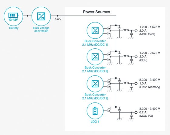
Although the main supply voltages for many FPGAs and SoCs have dropped dramatically, these are not the only supplies to consider. On-chip I/O supplies can cover a much wider range than the main logic supplies. Bulk supplies feeding POL regulators or Voltage Regulator Modules (VRMs) are often much higher voltage.
Although many scopes and probes can provide some DC offset, it may not be enough to deal with all the power rails in your system. And at lower volts per division (higher sensitivity) settings instrument systems tend to afford less offset. While blocking DC is an option, it is often undesirable (see above).
In addition to addressing the high-frequency needs outlined above, power rail probes such as TPR1000 and TPR4000 offer high offset range to address a wide range of voltage levels.
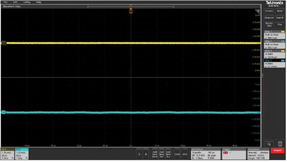
Measuring noise on the order of 10 mV requires careful attention to measurement system noise. As noted above, using non-attenuating, or 1X, probes reduces the burden on your oscilloscope’s amplifiers. The scope’s internal noise and measurement resolution also play critical roles.
The 6 Series offers 12-bit resolution at 12.5 GS/s. A High Res function boosts resolution to 16 bits at 625 MS/s and below. 4 and 5 Series MSOs also offer 12-bit resolution with up to 16 bits using High Res mode.
For PDNs powering FPGAs, processors and other complex IC’s, power rail impedances must be low in order to deliver high current in response to rapidly changing demand. However, the network is made up of many impedances including the voltage regulator, decoupling capacitors, and PCB traces. High-speed switching involves broadband frequencies and unexpected variations in impedance can result in excessive transients or noise. Measuring the impedance of a network design over a wide frequency range provides confidence that the network won’t produce unwanted surprises.
Network impedance measurements are traditionally performed using VNAs, such as the two-port TTR500 which can measure from 100 kHz to 6 GHz.
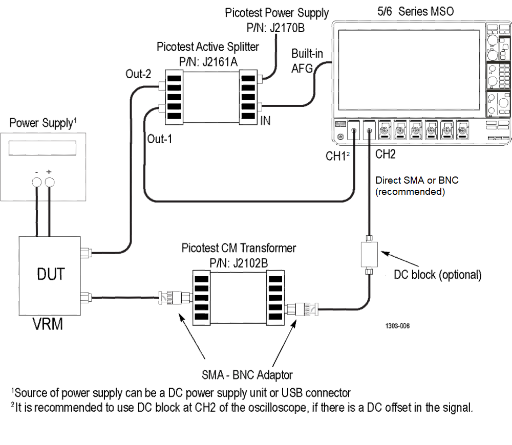
5 and 6 Series MSO oscilloscopes can measure power rail impedance down to 10 Hz using analysis software, a signal generator (built-in or AFG31000 Series), and an isolation transformer.
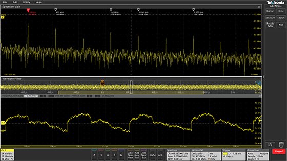
Let’s say you’ve measured the power rail noise and it’s out of spec. Is it coming from a DC-DC converter? The bulk supply? A PLL? A clock? Crosstalk? Spectrum analysis can provide clues to noise sources – helping to correlate noise frequencies to switching frequencies and harmonics.
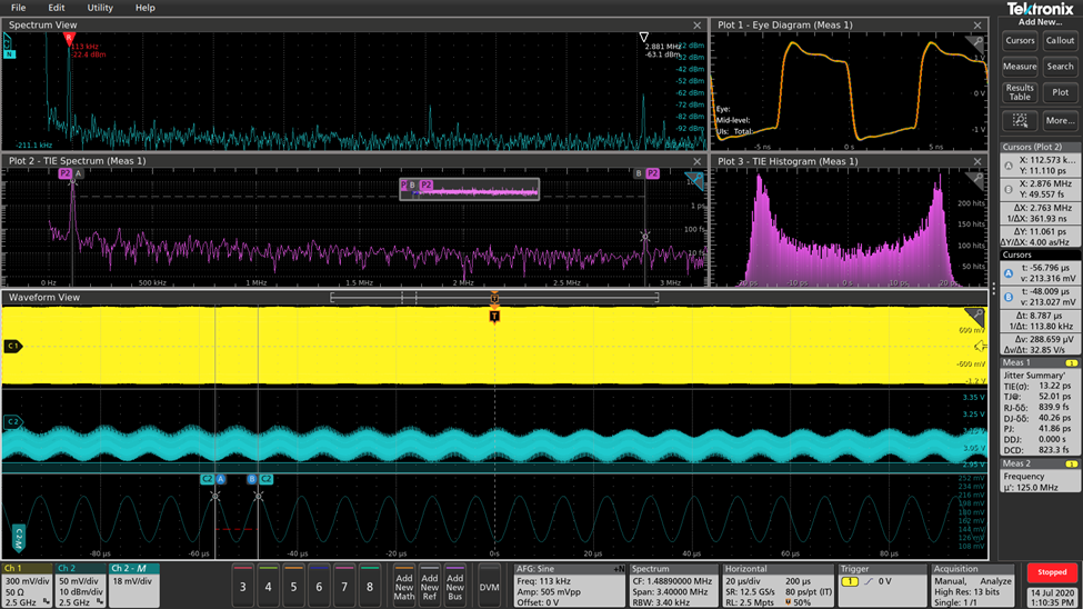
Noise on power rails often translates into jitter on high-speed data lines. Jitter and power integrity should be analyzed in both the time and frequency domains. Comparing periodic jitter (PJ) frequencies in the TIE spectrum to spurs in the power ripple spectrum is a fast and accurate way to identify signal integrity problems caused by a power distribution network (PDN). This type of analysis requires an oscilloscope with good spectrum analysis capability as well as good jitter analysis.
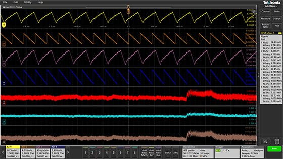
Making even simple measurements such as ripple, overshoot, and undershoot on dozens of power rails requires significant time and attention to detail.
The 5 and 6 Series MSOs are available with Digital Power Management software to automate these repetitive measurements and generate in-depth reports. The software also includes jitter analysis (TIE, RJ, DJ and Eye measurements) to check for excessive jitter on clocks and communications signals powered by your PDN.
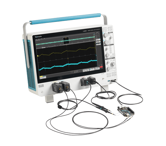
6 Series B MSO
Recommended for exceptionally low noise, 12-bit resolution, and up to 8 channels. From 1 to 10 GHz. Built-in arbitrary/function generator (AFG) recommended for impedance measurements
Noise Analysis
DPM software
Optional analysis software automates ripple, overshoot, under-shoot, turn-on, turn-off, time-trend, settling time, and jitter measurements
TPR Power Rail Probes
Low noise and high offset range at up to 4 GHz with DC offset ranging from -60 to +60 Vdc
Impedance Analysis
PWR software
Optional analysis software automates power quality, harmonics, amplitude, timing, switching loss, magnetic analysis, and frequency response analysis (control loop analysis, PSRR and impedance) measurements
Active Splitter (e.g Picotest J2161A, not shown)
Splits signal from oscilloscope’s AFG into an oscilloscope input channels and into the power rail under test.
Common Mode Transformer (e.g. Picotest J2102B-BNC, not shown)
Eliminates ground loop error in 2-port shunt-through impedance measurements.